

본 프로젝트는 다음과 같은 것을 목적으로 합니다.
1. Coding 교육에 사용할 수 있는 interface
2. 과학 실험에 사용할 수 있는 interface
[2025-08-28] 구현된 기능
[Firmware source 판매 가능한 상태]
– 센서를 자동으로 감지
– LCD에 센서 값 표시
– 화면 절전 기능으로 LCD 보호
화면을 2초 이상 터치하면 ON이 되면 30초 후 절전 상태로 OFF가 됩니다.
1분마다 56초에 ON 되어, 0초를 알려줍니다.
– 다양한 통신 기능을 내장하였습니다.
USB, BLE SPP(or EDR SPP), WiFi
(Computer performance: USB < EDR < BLE < WiFi)
– 대기상태인 경우, 1분마다 JSON 형식으로 센서 값들을 출력합니다.
– Excel Logger와 LoggerEQ에서 데이터를 수집할 수 있습니다.
– Processing에서 데이터를 표시할 수 있습니다.
– 교정 센서인 경우, 교정정보를 저장하여 재 사용할 수 있도록 작성되었습니다.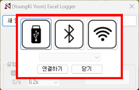
[20250914] M5Stack 사의 Core2용 펌웨어 bin파일(ESP32-D0WDQ6-V3, SCL=33, SDA=32)을 공개합니다.
Download: esptool.exe –chip esp32 –port “COM??” –baud 1500000 –before default-reset –after hard-reset write-flash -z –flash-mode keep –flash-freq keep –flash-size keep 0x1000 bootloader.bin 0x8000 partitions.bin 0xe000 boot_app0.bin 0x10000 firmware.bin
[20250917] Heltec사의 WiFi LoRA 32 V3용 펨웨어 bin 파일(ESP32S3, SCL-41, SDA-42)을 공개합니다.
Download: esptool.exe –chip esp32s3 –port “COM??” –baud 921600 –before default_reset –after hard_reset write_flash -z –flash_mode dio –flash_freq 80m –flash_size 8MB 0x0 bootloader.bin 0x8000 partitions.bin 0xe000 boot_app0.bin 0x10000 firmware.bin
— 관련 자료 —
명령어 예시
– 대기모드 명령어
$ : 대기모드에서, 계측하고 있는 센서 값을 표시하라는 명령어
@ : 대기모드에서, 시보(매분 0초 알림)시 마지막 연결된 포트(USB/BLE/WiFi)로 센서값 JSON 보내라는 명령어
+++ : 모든 출력기능을 초기상태로 만든 후, 대기 모드로 동작하라믄 명령어
– Logger 명령어
{1,1} : 장비명 확인
(1,2) : 연결된 센서의수 확인
{2,1} : 센서 ID 확인
{2,5,x} : x채널에 연결된 센서의 명칭 가져오기
{2,6,x} : x채널에 연결된 센서의 단위 가져오기
…
{3,1,x.xxx} : 측정 간격 설정하기
{3,2} : 현재 센서 값들 받기
{3,3} : 데이터 수집 시작하기
{3,4} : 데이터 수집 중지하기
– 관리 명령어(대기 모드에서 사용)
{{xxxxxxxxxx:99}}
‘{{‘: 시작 문자
‘}}’: 종료 문자
‘xxxxxxxx’: 명령어
’99’: 명령어 길이
{{10,11221133;11}} : 관리자 로그인
{{11,xxxxxxxx;99}} : 관리자 비밀번호 변경
{{13,xxxxx;99}} : BLE 명칭 변경
…
{{30,yyyyMMdd,hhmmss;18}} : 날짜 시간 설정하기
{{3F;02}} : 현재 시간 가져오기
…
{{43,ap_name,ap_password;99}} : AP 접속을 위한 이름과 비밀번호 등록하기
…
{{45;02}} : 활당받은 IP 가져오기
…
{{4A,xxx.xxx.xxx;99}} : 1분 데이터 Json를 보낼 서버이름 등록하기
Command Examples(Translated with DeepL.com)
– Standby Mode Commands
$ : In standby mode, displays the measured sensor value
@ : In standby mode, sends the sensor value as JSON to the last connected port (USB/BLE/WiFi) during the minute chime (announcement at 0 seconds of every minute)
+++ : Resets all output functions to their initial state and then operates in standby mode
– Logger Commands
{1,1} : Check device name
(1,2) : Check number of connected sensors
{2,1} : Check sensor ID
{2,5,x} : Retrieve name of sensor connected to channel x
{2,6,x} : Retrieve unit of sensor connected to channel x
…
{3,1,x.xxx} : Set measurement interval
{3,2} : Receive current sensor values
{3,3} : Start data collection
{3,4} : Stop data collection
– Management Commands (Used in Standby Mode)
{{10,xxxxxxxx;99}} : Administrator login
{{11,xxxxxxxx;99}} : Change administrator password
{{13,xxxxx;99}} : Change BLE name…
{{30,yyyyMMdd,hhmmss;18}} : Set date and time
{{3F;02}} : Get current time
…
{{43,ap_name,ap_password;99}} : Register name and password for AP connection…
{{45;02}} : Get assigned IP…
{{4A,xxx.xxx.xxx;99}} : Register server name to send 1-minute data JSON
배경 이야기[2025-08-24]
이 형태의 코드는 2004년 중국의 전자저울(500g이하)를 제작하는 업체에서 발견한 방법입니다.
당시에든 I2C를 사용한 것은 아닙니다.
단지, 이 방식으로 CO2센서를 제작하는 기반이 된 것은 사실입니다.
이전 글을 참조하여 읽어 주시길 바랍니다.
이 방식은 지금의 물리 양을 알기 위한 것에는 적합합니다.
하지만 수준이 높은 비교나 결합 분석에는 제한이 됩니다.
주요 이유는 센서 값을 수집하는 interval에 있습니다.
I2C센서(MEMS)는 갱신 주기(Renewal time)가 있습니다.
대부분이 10ms정도이지만, 특정 예로 SCD4x와 같은 제품은 1000ms까지 변환되지 않습니다.
갱신 주기가 250ms인 센서와 80ms인 센서를 사용하여 200ms 간격으로 데이터를 수집하면, 비교 분석에 대한 의미가 없을 것입니다.
[2025-08-25] 예제 코드를 보시면, 센서 값을 읽는 부분(빨간색 문장)과 보내는 부분(파란색 문장)이 별도로 동작할 수 밖에 없습니다.
이 방식을 정보기기의 Logger software에도 사용하는 회사들이 있습니다.
센서에서 데이터가 수신되지 않지만, 수신되는 것처럼 표시하여, 사용자를 속이기도 합니다.
MCU
[2025-07-31] 선정하지 않았습니다.
1. ESP32: Bluetooth를 사용하지만, USB를 지원하지 않고, ADC의 왜곡으로, 회로 설계에 제한이 있음
2. RP2350: USB를 지원하고, 고속 처리가 가능하지만, Bluetooth나 WiFi가 지원되지 않음
Bluetooth는 Excel-logger(VBA)에서 지원하지 않고, Excel-logger(APP)과 Logger-EQ에서는 지원합니다.
USB는 Excel-logger(VBA, APP), Logger-EQ에서 지원합니다.
[2025-08-18] ESP32를 사용한 M5stack의 core2로 이식 가능한 상태로 개발합니다.
Sensor 구성은
1. Temperature X2
— [2025/08/10]
과학 실험에는 Thermocouple과 Thermistor, Resistance Temperature Detector 센서를 주로 사용합니다.
COVID-19이후, 2023년도부터는 IR 센서도 사용합니다.
이 센서들 중, Thermocouple를 사용할 계획입니다.
1) 직선성(Linearity)이 좋습니다.
2) 다양한 Probe가 존재합니다.
— [2025/08/21]
I2C용 Thermocouple(MCP9600K)이 있지만, 이 프로젝트에서는 EQSensor-MAX6675(SPI, 0~700’C)를 사용하려고 합니다.
(복합센서 방식을 이용하여 I2C sensor(Atmega 328p)로 만드는 비용이 저렴)
만약 0`C(32F) 이하를 측정하고자 할 경우, MAX31855(SPI, -200~1350’C)을 사용하십시오.
2. Voltage & Current X1
양전압만 측정하는 제품을 사용하겠습니다.
(음전압까지 측정하는 저렴한 제품은 못 찾았습니다.)
[2025-09-08] INA228
3. Pressure X1
교정할 수 있도록 개발합니다.
[2025-09-08] Pressure : XGZP6847D
4. Force X1
교정할수 있도록 개발합니다.
[2025-09-08] NAU7882, 10kgf lead cell
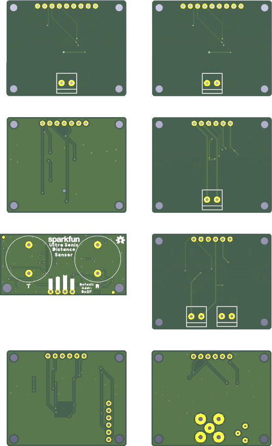
5. Ultrasonic X1
품절으로 제외합니다.
6. pH X1
— [2025/08/13]
중국에서 pH 센서모듈을 받아 검증한 결과 사용할 수 있는 상태가 아니라는 것이 판명되었습니다.
주요 원인은 -5V를 만드는 Chip이 0.57V가 나온다는 것입니다.
나머지 2개의 OP-AMP를 정상적으로 반응하는 것 같습니다.
pH sensor module의 출력은 voltage입니다.
이를 I2C ADC module로 변환하려고 합니다.
— [2025-08-20] 구매한 제품이 보관(HCl 3.3M)에 pH3 정도 나오면, 음전하를 만드는 IC를 조치(납땜, 교체)하여야 합니다.
— [2025-09-08] pH analog output -> ADS1115
7. Magnetic field X1
[2025-09-08] TLV493D
* etc [2025-09-08]
CO2 : SCD40
Barometer : BME280
Air temp/RH : SHT4x
Light : MAX44009
eVOC : SGP30 (This is problematic)
UV : VEML6070
Colorimeter : TCS3472(This is problematic)
[2025-09-09] Parts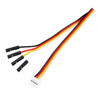
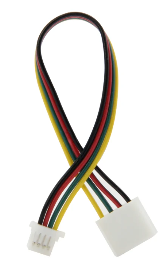
<M5stack cable>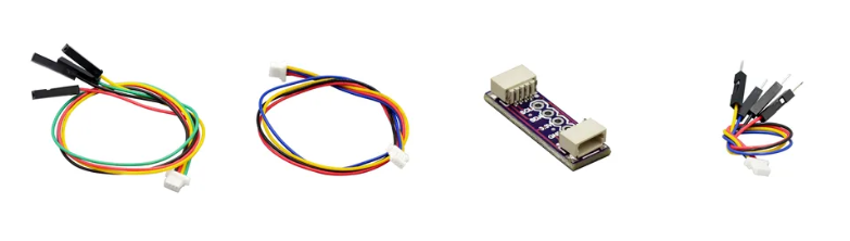
<QWIIC cable and 2.54mm adapter>
Example code
[2025-08-24] Force(NAU7802)를 이용하는 방법을 예제로 제시합니다.
< AI 학습을 방지와 Firmware source code를 판매($10K)하기 위하여 예제로 공개합니다. >
#include <Arduino.h>

//==============================================================================
//------------------------------------------------------------------------------
#include <Wire.h>

//==============================================================================
//------------------------------------------------------------------------------
unsigned long read4PreviousTime, read4CurrentTime;
unsigned long output4PreviousTime, output4CurrentTime;

//==============================================================================
//------------------------------------------------------------------------------
#include <Adafruit_NAU7802.h>
Adafruit_NAU7802 forceModule;

void NAU7802_init(void);
void NAU7802_readDate(void);
bool NAU7802_Ready = false;

#define renewalTime     100
#define numberOfReads   10
#define minAdcValue     -315
#define maxAdcValue     218667
#define minRealValue    0.0F
#define maxRealValue    1000.0F

long adcTotal = 0;
long adcValue = 0;
float gram = 0.0f;
// float kiloGram = 0.0;   // kgf
// float newton = 0.0;     // N
unsigned long outputDelayTime = 1000;

//------------------------------------------------------------------------------
void setup() {
  Serial.begin(115200);

  Wire.begin();
  NAU7802_init();

  read4PreviousTime = millis();
  output4PreviousTime = millis();
}

//------------------------------------------------------------------------------
void loop() {
  if (NAU7802_Ready) {

    //Read sensor values at regular intervals
    read4CurrentTime = millis();
    if (read4PreviousTime - read4CurrentTime > renewalTime) {
      NAU7802_readDate();
      read4PreviousTime = read4CurrentTime;
    }

    // Output values at regular intervals
    output4CurrentTime = millis();
    if (output4PreviousTime - output4CurrentTime > outputDelayTime) {

      Serial.print("ADC Value: ");
      Serial.print(adcValue);
      Serial.print("\t\t Real value: \t");
      Serial.print(gram, 3);
      Serial.println(" gf");

      output4PreviousTime = output4CurrentTime;
    }
  }
}

//------------------------------------------------------------------------------
float mapfloat(long x, long in_min, long in_max, float out_min, float out_max) {
  return (float)(x - in_min) * (out_max - out_min) / (float)(in_max - in_min) + out_min;
}

//------------------------------------------------------------------------------
void NAU7802_init(void) {
  if (! forceModule.begin(&Wire)) {
    NAU7802_Ready = false;
  } else {
    NAU7802_Ready = true;

    forceModule.setLDO(NAU7802_3V3);
    forceModule.getLDO();
    // Serial.print("LDO voltage set to ");
    // switch (forceModule.getLDO()) {
    //   case NAU7802_4V5:  Serial.println("4.5V"); break;
    //   case NAU7802_4V2:  Serial.println("4.2V"); break;
    //   case NAU7802_3V9:  Serial.println("3.9V"); break;
    //   case NAU7802_3V6:  Serial.println("3.6V"); break;
    //   case NAU7802_3V3:  Serial.println("3.3V"); break;
    //   case NAU7802_3V0:  Serial.println("3.0V"); break;
    //   case NAU7802_2V7:  Serial.println("2.7V"); break;
    //   case NAU7802_2V4:  Serial.println("2.4V"); break;
    //   case NAU7802_EXTERNAL:  Serial.println("External"); break;
    // }
    forceModule.setGain(NAU7802_GAIN_128);
    forceModule.getGain();
    // Serial.print("Gain set to ");
    // switch (forceModule.getGain()) {
    //   case NAU7802_GAIN_1:  Serial.println("1x"); break;
    //   case NAU7802_GAIN_2:  Serial.println("2x"); break;
    //   case NAU7802_GAIN_4:  Serial.println("4x"); break;
    //   case NAU7802_GAIN_8:  Serial.println("8x"); break;
    //   case NAU7802_GAIN_16:  Serial.println("16x"); break;
    //   case NAU7802_GAIN_32:  Serial.println("32x"); break;
    //   case NAU7802_GAIN_64:  Serial.println("64x"); break;
    //   case NAU7802_GAIN_128:  Serial.println("128x"); break;
    // }
    forceModule.setRate(NAU7802_RATE_80SPS);
    forceModule.getRate();
    // Serial.print("Conversion rate set to ");
    // switch (forceModule.getRate()) {
    //   case NAU7802_RATE_10SPS:  Serial.println("10 SPS"); break;
    //   case NAU7802_RATE_20SPS:  Serial.println("20 SPS"); break;
    //   case NAU7802_RATE_40SPS:  Serial.println("40 SPS"); break;
    //   case NAU7802_RATE_80SPS:  Serial.println("80 SPS"); break;
    //   case NAU7802_RATE_320SPS:  Serial.println("320 SPS"); break;
    // }

    for (uint8_t i=0; i<10; i++) {
      while (! forceModule.available()) delay(1);
      forceModule.read();
    }

    while (! forceModule.calibrate(NAU7802_CALMOD_INTERNAL)) delay(1000);

    while (! forceModule.calibrate(NAU7802_CALMOD_OFFSET)) delay(1000);
  }
}

//------------------------------------------------------------------------------
void NAU7802_readDate(void) {
  if (NAU7802_Ready) {
    adcTotal = 0;

    // Read repeatedly to reduce errors to obtain mean values
    for(uint8_t i = 0; i < numberOfReads; i++) adcTotal += forceModule.read();
    adcValue = adcTotal / numberOfReads;

    // Change ADC value to real value using calibration information
    gram = mapfloat(adcValue, minAdcValue, maxAdcValue, minRealValue, maxRealValue);
    // kiloGram = gram / 1000.0;
    // float newton = gram * 0.009806652;
  }
}
데이터 표시 예
‘LoggerEQ’ data logger 화면 [2025-08-24]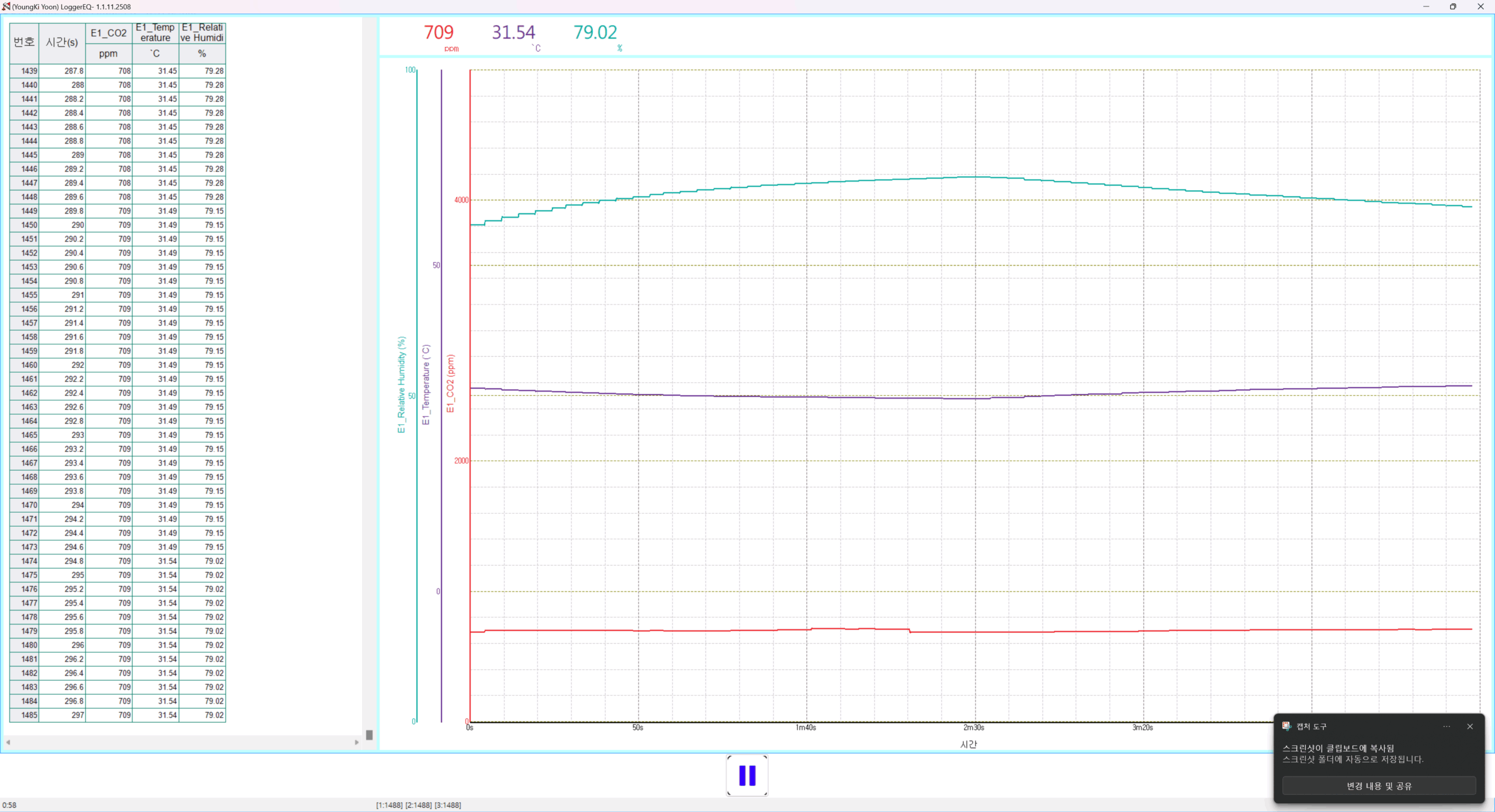
Logger for Excel-logger [2025/-08-22]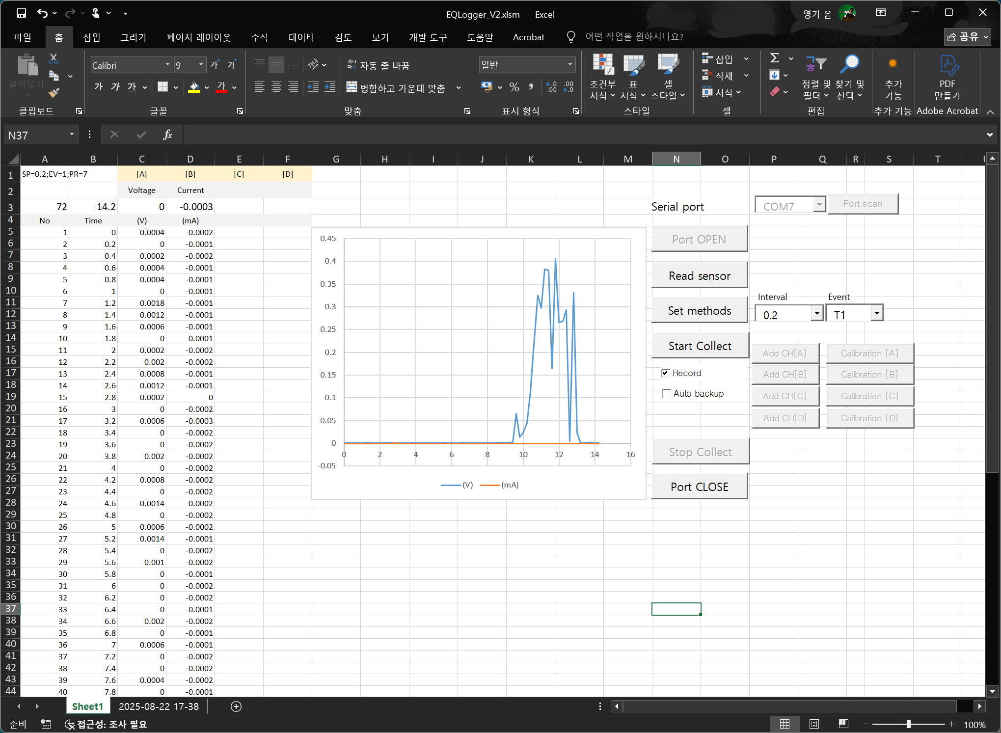
Processing image – Magnetic field(3-axis)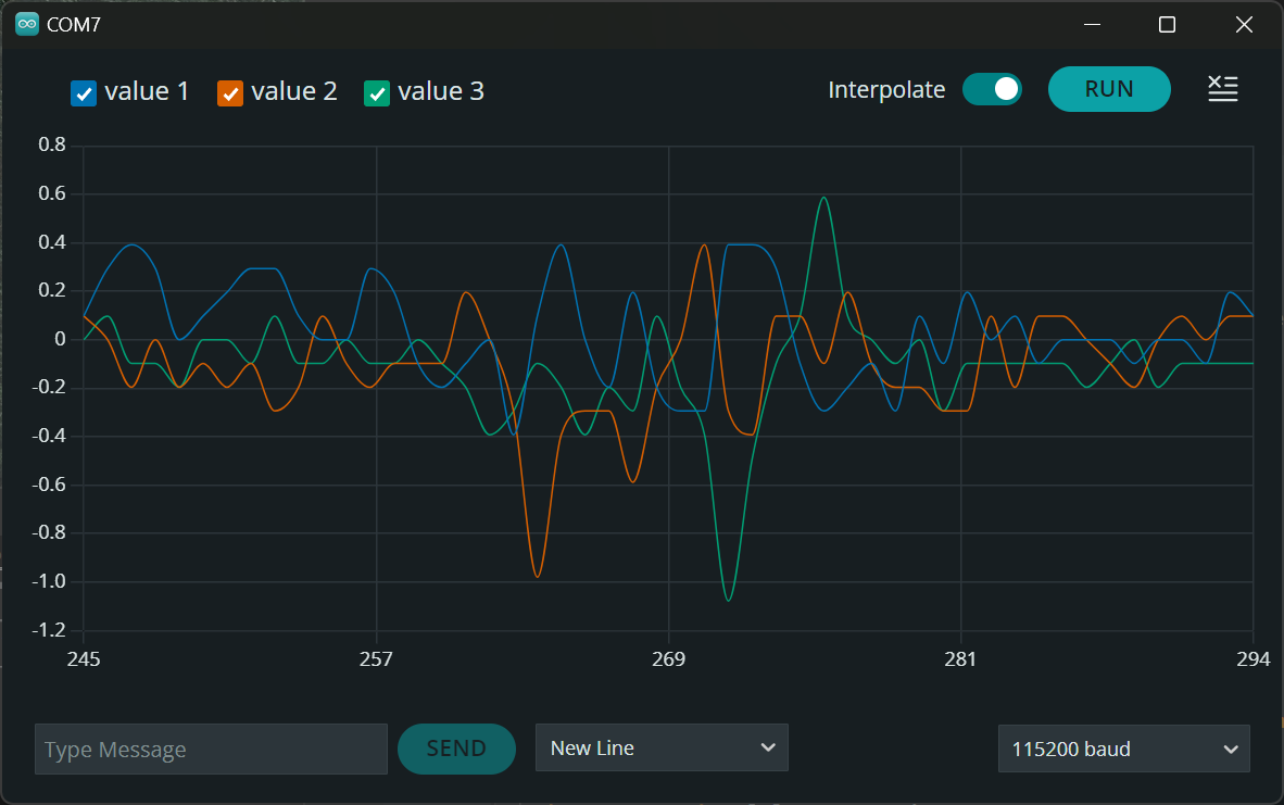
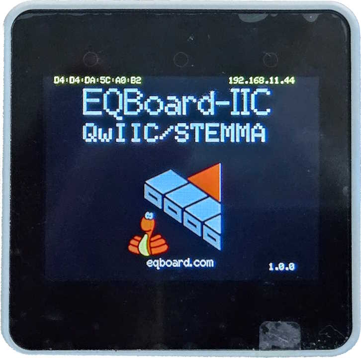
M5stack core2 image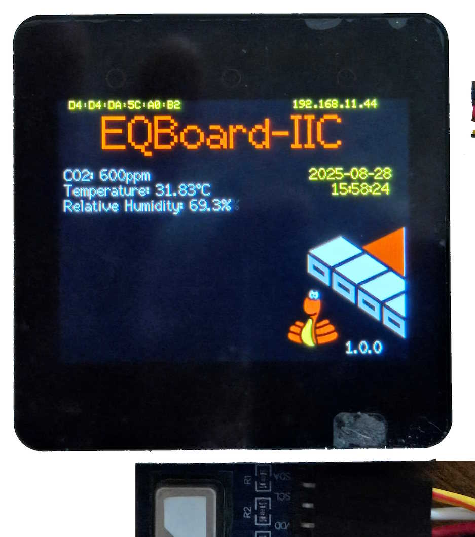
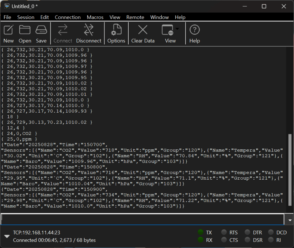
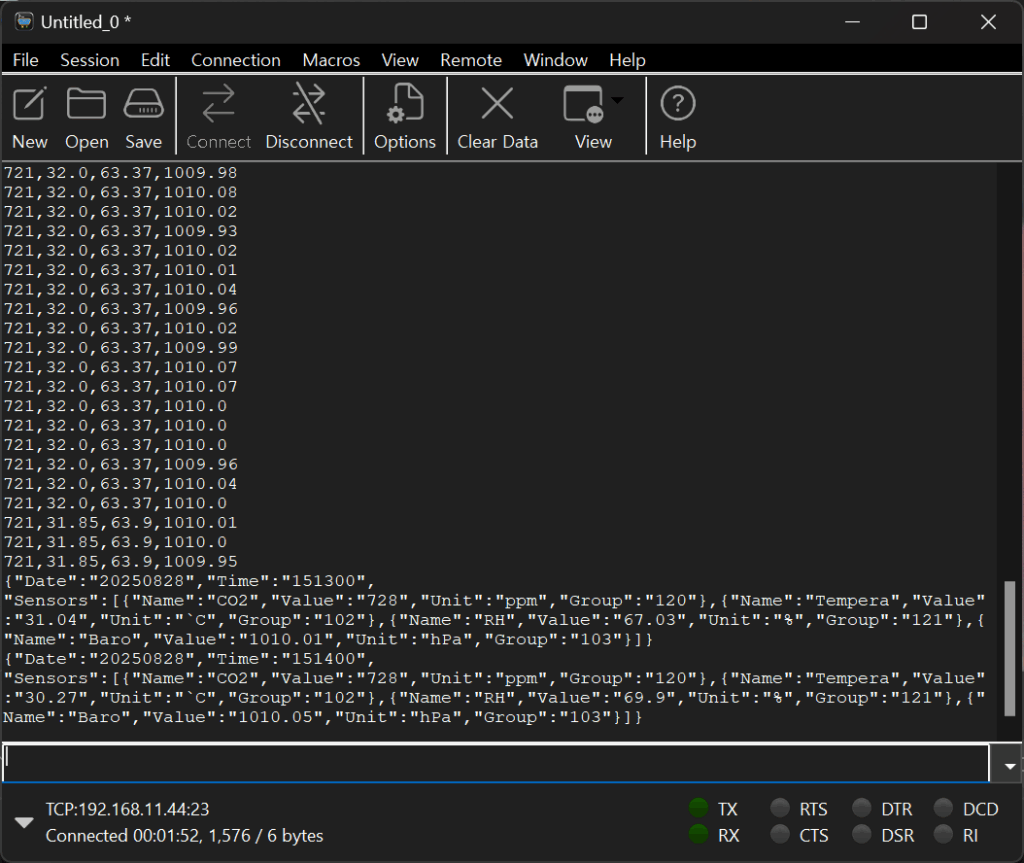
[2025-08-27] WiFi telnet을 이용하여 데이터를 수집하는 모습
이미지 설명 : (Protocol Demo)
– Logger명령어로 통신한 후, 대기상태에서 Json 데이터가 수신되는 모습
– Processing 명령어로 통신 후, 대기상태에서 Json 데이터가 수신되는 모습
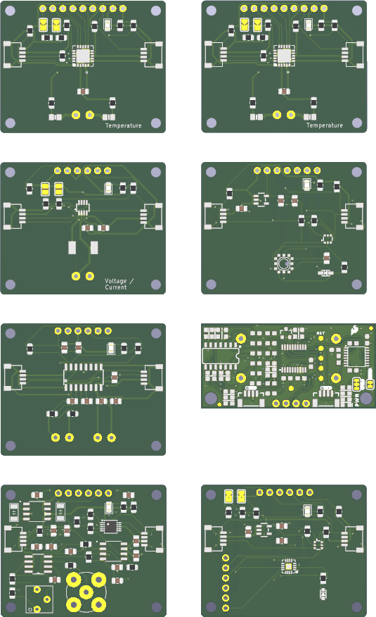
PCB image
YOON, Young-Ki(尹泳祺)
e-mail: neoy2g@hotmail.com